Knowledge database
Do you have some special knowledge
or a handy hint ?
Send it to
Read the Terms of Use before reading further
Directory
Hino
Rainbow - Wikipedia, the free encyclopedia
Air Cleaner Filter
Found huge differences in cost.
Repco sell Ryco HDA 5735 - cost $264.00 (10% off for RAA)
Fleetguard AF25231 - cost $68.00
Kevin
Ed - Multispares sell them for 47.95
 to top
Air Con Gas
Originally the RB145A buses would have been charged with 'R12' which is a hydrocarbon gas.
As part of the import process these should have been converted to 'R134a' which is still
the most common gas used in Australia.
The downside to this is that R134a will slowly leak, requiring a top up after some years.
Australian supplied buses (RB145K) would have been charged with R134a originally.
Bob Wood
to top
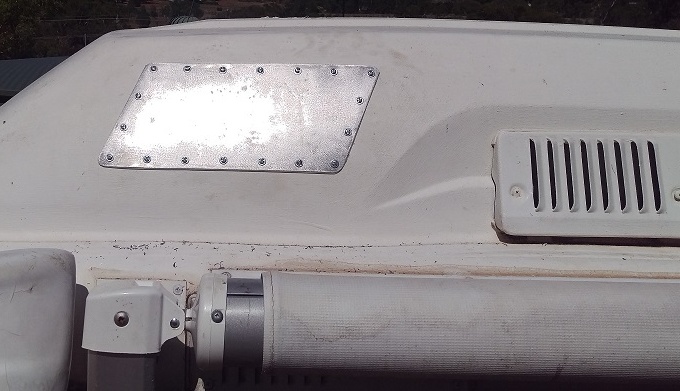
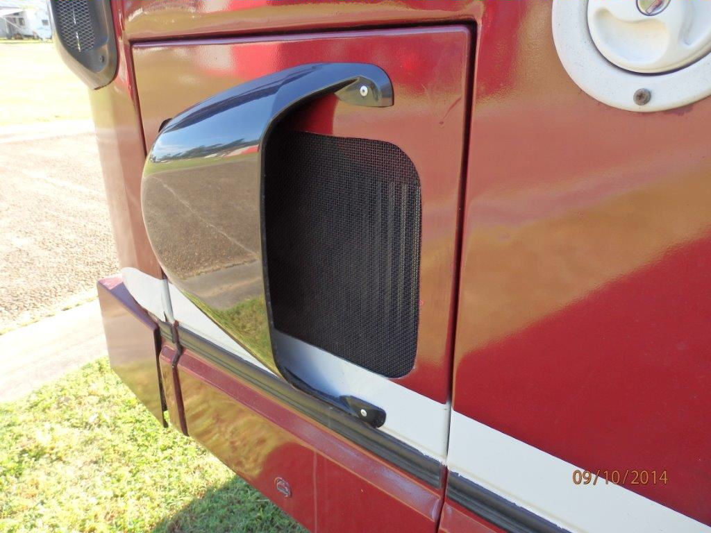
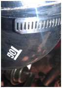
Air Con Lab le
Sometimes there will be a label on the filter, which is inside the vented panel on the RH side behind the front wheel.
Bob Wood
to top
Engine Serial Number
Read the owners manual ! Page 16
to top
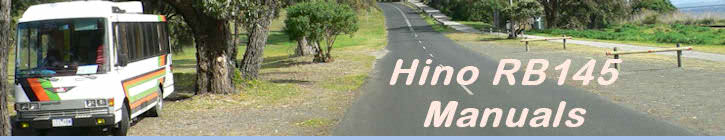
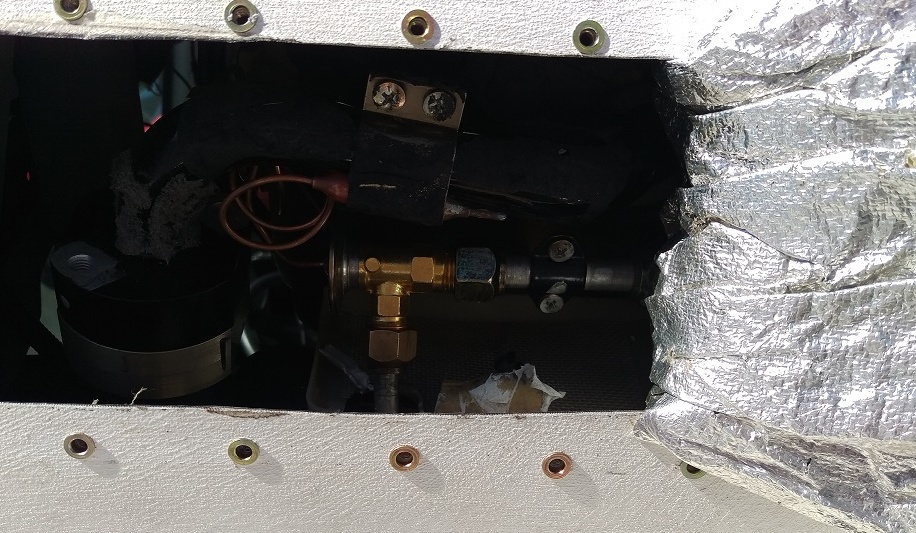
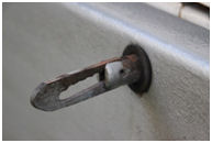
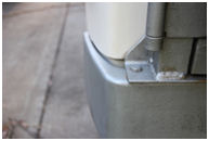
Air Tx valve change
When my aircon stopped working the first diagnosis found a leak on the compressor.
After having it rebuilt with all new seals it still leaked, indicating a blockage in
the system which proved to be the Tx valve. Now the Tx valve is the original component
around which Hino built the bus!
It's on the upper side of the LH end of the 'hump' aircon unit. The simple and lowest
cost solution was to cut a hole in the roof (in the right place) to enable the valve to be changed.
The alternative would have been to remove the entire aircon unit from the hump.
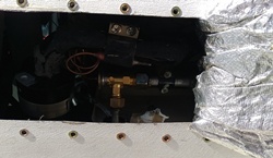
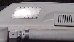
All now working as it should with rebuilt compressor, new Tx valve, new filter and new gas.
The cover required a little hand-beating to get the curves right and a gasket to seal it.
A couple of coats of paint now to finish it off.
Cheers Bob
to top
Engine Serial Number
Read the owners manual ! Page 16
to top
Vehicle Identification Number
Read the owners manual ! Page 16
to top
Clutch travel
RB145a Clutch travel
I have had an ongoing issue with the clutch, too much travel resulting in unsatisfactory gear shifts.
I have rebuilt both cylinders and replaced the ball joints on the gearbox end of the shift cables but the problem remains. But now I have found it!
If you squirm in on your back under the dash so that you can move the clutch pedal with one hand and put the other on the clutch pedal pivot bearing and
move the pedal you might find a lot of play. On mine there is a spherical carbon bush held between two plates and this bush had crumbled up to almost
nothing resulting in a lot of slop and pedal travel before the cylinder moved.
Go to the bearing shop and get a basic sealed bearing with a 15mm bore and
jamb it in between the two plates and winch the two retaining bolts up. Job done for less than $20 and the clutch is great.
I did not even try and go looking for the OE part.
Regards,
Paul carter
to top
Isolation switch
There are two.
One is on the right at the bottom of the dash,
a pull in / out and turn at same time;
The other inside the engine bay, on the left hand side on a panel, a
flip up / down switch. Use this when working on the engine to protect yourself.
to top
V Belts
I just replaced all the V belts and have the Gates
part numbers as follows:
Vacuum pump - Gates XL9355 - 12mm x 911mm
Alternator & A/c
- 2 x Gates TR24538 - 17mm x 1380mm
Power Steering
- 2 x Gates XL7455 - 10mm x 1171mm
Total cost from
Statewide Bearings (Gates Distributor) $100.65
Best
regards Bob
to top
Engine cutout (mystery solved)
Engine cut outs solved!
Our 1987 RB145 has an engine stop system using a vacuum actuator which is controlled
by a solenoid valve.
The bus has always started easily, run well and give good fuel consumption with
the one embarrassing and potentially dangerous limitation that at 2700-2800rpm
under load, the engine would suddenly cut out. It would then require a wait of
some 10 seconds or so before it could be re-started. Once re-started, performance
was completely normal.
As well as consulting with other RB145 users, engine specialists, auto-electrical
specialists, diesel specialists etc. I have spent many, many hours poring over
the manuals and circuit diagrams for this bus, trying to understand the logic
of what was happening. Testing proved that this cut-out did not occur while free
revving in neutral, which led me to study the wiring diagrams, where the only
circuit that included the neutral switch and rpm
pick-up was the warm-up program. Disconnecting the warm-up controller made no
difference so after numerous other electrical tests the engine stop solenoid
was rewired to be powered directly from the ignition switch. Again, no change.
Since there are two solenoid valves in close proximity I also checked the idle-up
solenoid in case there was some unwanted interaction. That just about ruled out
the electrics as the culprits.
I then went on to study the vacuum system, again could not find any possible
cause for what was happening. In such a generally simple engine system, we were
running out of possible villains.
Further road testing showed that by running downhill in a lower gear, the engine
would spin up to 3000rpm quite happily but then applying the accelerator caused
it to cut out immediately.
After further consultation with experts it was concluded that the problem had
to lie in the injection pump/governor. Further consultations with the fuel injection
experts agreed that the pump had to come off for a proper evaluation on the test
bench. So, the injection pump was duly delivered to the FInj. intensive care
department where it was ultimately given a clean, if expensive, bill of health.
Talking through the problem with one of their people,
he asked about the air piping leading to the turbocharger.
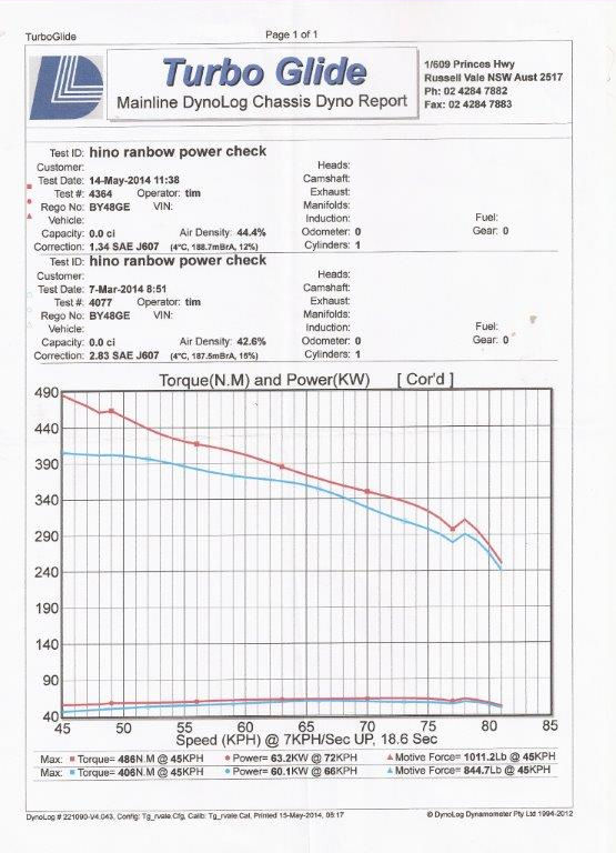
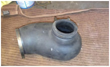
Back home I carried out a very detailed inspection
of the entire air system which revealed a tell-tale
imprint inside the large rubber molding that connects
directly to the turbocharger. Under high airflow conditions
while under load, this rubber molding was being sucked
flat across the air inlet to the turbocharger, cutting
off the air supply.
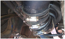
 The molding is available ex Japan at considerable expense ($350+ in 2011) so
has now been replaced by an adaptation made from a silicon reducing elbow, a piece
of mandrel bent aluminium tube and a silicon joiner.
The molding is available ex Japan at considerable expense ($350+ in 2011) so
has now been replaced by an adaptation made from a silicon reducing elbow, a piece
of mandrel bent aluminium tube and a silicon joiner.
The result, perfect. While accelerating I can now
let the engine run up to 2900-3000 rpm without fear
of an instant cut out, and when necessary, I can keep
up with the traffic at 100kmh.
(I bet few saw that cause coming. Excellent write up Bob - Ed)
to top
Steering slack / back
lash
Since I have had my Hino, I have been bothered by what
I felt was excessive backlash in the steering. By chance
I discovered that the backlash is adjustable - so I
did it. Made a world of difference to the "feel" of
the drive and controllability of the vehicle on the
highway. If anyone is experiencing similar problems
contact me and I will point you in the right direction.
Steve McDonald
That's good you have been able to improve things. Have
you visited Ron's website?
You will find it contains both workshop manual and
parts manual for the RB145 with full details of the
steering box adjustment you have done. The trap with
this type of steering box is that if all of the slack
is adjusted out in the centre, it can become stiff
at the outer ends (full lock). There is also the possibility
of play in the sliding shaft that connects the steering
wheel to the steering box. Bob Wood
to top
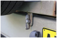
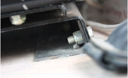
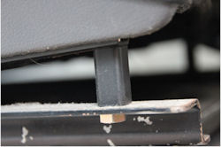
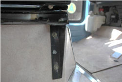
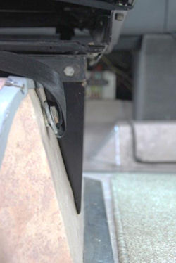
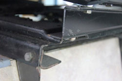
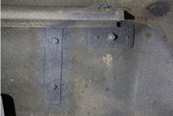
Engine mounts
Had reason to check my engine mounts and found one
had parted. Not sure they were correct parts anyway.
Solution was to fit Mackay #A2509 mounts which require
slight mod to the engine brackets, ( see
pic attached ). Also, due to the limited space
around the RB145 engine, it is necessary to loosely
fix mounts to brackets before re-fixing brackets to
engine. Then with the jack removed from under the engine,
tighten everything.
The mounts are available from most auto parts suppliers
for around $70 per pair.
One post script. After installation and settling, I
found I had to add a 5mm thick packer under each mount
to bring the crankshaft pulley bolt in line with the
hole in the cross-member. I cut them from 5mm steel
plate. 1 x 12mm hole then jigsawed down to make a slot.
Bob Wood
to top
Expansion Tank
The expansion tank, it will never remain full ! As
the water in the engine heats up it expands, and it
must go somewhere. On cooling it contracts, thus the
expansion tank empties. It is ok to go down to say
half way or even less, just keep an eye on it and as
long as it does not empty, you do not have a problem.
And do not open the system more than you need to, you
let air in and this causes corrosion, or could do,
should not if you have correct additives. Also, you
have a low level light and alarm, so wait until it
goes off, if it does in short time you have a leak,
if not you do not have a problem. I do not look at
my water level - at all - until either the alarm /
light comes on or I need to change the whole systems
water.
to top
Overheating - fans
Had trouble overheating going up long steep hills.
The trouble was one of the front fans wasn't working
which caused the other fan not to work.
They are 12volt fans. One won't work without the other.
Do a circuit test.
One of the brushes was sticking. Easy to fix and solved
the problem.
Brian
to top
Door top guide roller
This roller will eventually wear out and may cause
the door to rattle.
No idea where to find a replacement, but it can be
made out of a nylon rod on a lathe.
Anyone got another option please
to top
Brake Pedal Assembly
Removal
When I came to do this job I found the manual was somewhat
lacking. Must have been lost in the translation! Hopefully
these notes will make it easier for someone.
Brake Pedal Assembly Removal
Bob Wood
to top
Auto Cooling
Auto Cooling Pty Ltd, Factory 7 / 216 Blackshaws Rd,
Altona Nth VIC. Ph. 03) 9362 7799
to top
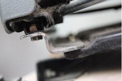
Engine shutoff fails
There are many possible reasons for the engine failing
to shut off, but a common item to wear and fail is
the engine shutoff vacuum operated switch.
It can be found on page 19 of the motors workshop manual
just to the left and above the number 27, or in this
image.
This item needs to be removed, an easy procedure, and
the two main parts separated by unbending the retaining
lugs.
Inside, the rubber diaphragm will be found to have
a split.
This can be repaired by using a rubber glue that remains
flexible, eg. a shoe repair glue, and placing a thinnish
flexible blob over the split.
Reassemble and reinstall.
This repair will survive for quite some time, and saves
you a fortune !
to top
Gravel and sand roads
When traveling on gravel roads, reduce your speed and
reduce tyre pressure.
This will substantially reduce the risk of tyre failure,
and other damage from flying rocks.
On sand, reduced pressure improves traction and reduces
sinking.
Be sure to reinflate tyres when back on the seal.
to top
Tyre pressures
When an RB145 bus fitted as a motorhome is fully loaded,
the gross weight will be close to 6 Tonnes.
According to tyre charts, front tyres need to be 10
ply minimum and operate at 75 psi (5.17 bar) and rear
tyres need to be 12 ply at 85 psi (5.86 bar).
(Tyre pressures depend on the make of the tyre so check
for your tyres.)
However these pressures results in a harsh ride and
increases the possibility of tyre damage.
It is recommended to have tyre pressures at; front
70 psi (4.83 bar) and rear 75psi (5.17 bar). For these
pressures, 10 ply tyres may suffice.
This also improves steering and may reduce sway if
your vehicle suffers from this.
The increase in fuel consumption is not significant.
Links here,
and here (light
trucks).
to top
Springs and dampers
Hino RB145 buses converted to motorhomes are at the
maximum weight for the spring sets, and adding an extra
leaf to each spring set dramatically improves the ride,
and avoids or reduces bottoming out.
Haire
Truck & Bus Repairs Wodonga, Victoria, do an
excellent and price competitive job.
Wilkinson's
Engineering Atherton, Queensland, possibly
do the best job in the country. Not only do they add
a leaf to each spring set, but each set is removed
and individually retempered.
Powerdown is
the pioneer and leading supplier of Australian designed
shock absorbers and suspension components for trucks,
buses, 4WD's and European vans. Our shock absorbers
have been specifically designed for Australian roads
and climatic conditions. Powerdown has an extensive
distribution network throughout Australia and New Zealand.
Phone 02 4949 0000.
Front Shock absorber, RT 336. (road train)
Rear Shock absorber, RT104M3, heavy duty, non adjustable
with bushings to fit
Cost $225 per pair (2013)
Be sure to check the dampers (shock absorbers) are
working, or have them replaced.
to top
Windscreens
O'brien
Glass Product # 818991
Koala
glass
to top
Air Conditioner V Belts
Any one who has had to purchase V belts may have received
a shock at the price.
Well the other day the air con did not work and I thought
it had lost it's gas.
After organising an appointment at an air con fixer
place, I decided to check if the engine was still in
the housing as it has performed flawlessly for some
long time, actually since the last oil change, and
lo and behold, the air con belts were not there !
Well only the remnants remained. So being computer
savvy I decided to look on line and found the first
link to be Super Cheap Auto. Yes they had the right
size, code 11A1130M and only $19.99 for the pair !!!
Not only does the air con work better, I am a happy
and cooler man.
Ron
PS if any one purchases the belts for the alternator
or the steering pump, please pass the code onto Admin,
email at top of page - thanks.
Bob has written - see Belts - V Belts
to top
Air conditioner compressor
Air conditioner compressor replacement. Sanden model
part number cxs7867, sd7h15 it is a universal type
and you will need an adapter plate.
to top
Reading oil dip stick
I would like to know how to read the oil dipstick,
there are no marks showing low or full however there
appears to be a very small slot approximately 25mm
long but showing no levels, I am only guessing the
bottom of the cutout is low and the top is full but
this only a guess and that I do not like. My motor
is the W40C-T. I presume they are all similar ? Norm
Norm, You are right, that is how Hino does the oil
levels. You are also right regarding the motor, they
are all W40C's and the T is for turbo-charged. Another
way to check the oil, when you do an oil change, put
on a new filter, add exactly 11 litres, start the engine
to fill the oil ways and filter, and then stop, wait
a minute for the oil to settle and then check the oil
measuring stick, and it should be on the full mark,
or top end of the slot. All the best, and thanks for
the question, glad to be able to help. Happy travels.
While on the subject of oil, grade to use is 15W40,
and change oil and filter every 10,000 km. At the same
time, clean the air filter. Try and grease the nipples
every 5,000 km.
to top
RB145 on car license
There is a person advertising an RB145A for sale on
Gumtree and also advertising that it can be driven
on a car licence. Somehow he's had it de-rated to a
GVM of 4495kgs to bypass the light rigid driving licence
requirements and also the yearly safety inspections.
Problem is, as we all know, is that you cannot get
a fitted out RB145 under 4500kgs under any circumstances,
so if some poor person buys this vehicle believing
they can, they will certainly be in trouble if the
vehicle is weighed by state transport authorities and
worse still, if they are unfortunate enough to have
an accident, their insurance may be void (refer to
Collyn Rivers latest article in the Wanderer). I would
just ask that if you know someone considering a Hino
that you please point this out to them so they don't
get caught out.
Cheers, Les
Ed comment - the tare weight of the RB145 without the
seats is 4495 kg. When fitted out, with full tanks
and ready for the road, the GVM is close to 6000
kg.
to top
Hino extra radiator
The Australian assembled RB145 has an extra radiator
behind the air conditioner condenser on the right hand
side of the bus.
The imported RB145A's don't have this extra radiator
and I was wondering if any of these owners have had
any overheating issues whilst traveling Oz? I've heard
of an owner who added extra cooling for towing but
that's all. Perhaps our 'group' can shed some light
on whether their vehicles cope ok without the extra
radiator?
When I remove my small radiator I was planning on using
'blank off' rubber caps 16mm I think they are, plus
hose clamps obviously, to ensure the water flows straight
through to the front radiator and back again.
Admin - I have driven in 40 degree heat full throttle
up the steep central divide mountains in third gear
for a long time, and no overheating. The temperature
gauge will rise much hotter than normal as
per the owners manual until the electric fans
start, and right to the top of the normal zone, but
this is below the RED zone. I have heard on more than
one occasion of owners modifying cooling systems as
they believed their units were over heating, but this
is not the case.
photos from Les Trask
.jpg) .jpg)
.jpg) .jpg)
to top
Bus heater system removal
Hi my Hino RB145 has a water pump in front of the left
side rear wheel which was for the heater system I think.
I have removed the heaters and would like to remove
it and the redundant pipes, as I would like to fit
a water tank there. Can anyone tell me if this possible?
Gary
Gary, the water pump and diesel heater unit you
are referring to is to heat the engine water system
for the bus in the extreme cold of Japanese winters.
It is possible to remove this system in total as well
as all the bus interior heaters along with all the
pipe work from the engine and return.
The electrics need to be disconnected beneath the floor
and the terminals protected from the environment by
sealing in a plastic bag and securely tied to the chassis.
PS On the other side of the bus is the diesel heater
unit to keep the system from freezing in the -30C temperatures
of the Japanese winters. This can also be removed.
Seal the diesel line that comes from the tank. This
line can be used to supply diesel to a diesel heater
unit to heat the bus internally to great effect.
Note: the outlet to this line is not at the bottom
of the tank, so you can not run out of fuel for the
engine, or put another way, the fuel will stop flowing
here before the tank is empty, just in case you wonder
why the heater stopped when there is still 10 or 15
litres of fuel in the tank - Ron
to top
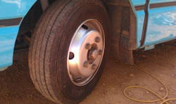
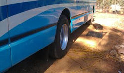
Tubeless tyres
After a lot of searching I stumbled over a useful source
of 17.5 x 6.00 tubeless rims with the correct 5 stud
centres and 127mm offset.
These allow the use of 215/75 or 205/80R17.5 tubeless
tyres and fully comply with the Hino parts manual.
For anyone interested, contact Dave or Nathan at Tyreright,
Wangara WA
Tel. 08 9302 5055 or info@wangara.tyreright.com.au.
They import them by the container load for NW mining
use and sell them at $170 each.
Cheers Bob Wood .
Admin - I asked Bob if he could
give an insight into the use of the tyres - here
is his reply.
When I bought the bus it was
sitting on 17.5 x 5.25 tubeless rims which had 115mm
offset and 8mm centre thickness. I now know these
were commonly fitted to the somewhat lighter Hino
Dutro trucks as well as Toyota Dynas. The tyres were
215/75 Yokohamas on the front and 205/80 Bridgestones
on the back and were all in very good condition.
I found it had some tendency to wander and all the
usual swaying problems.
The swaying was largely tamed by replacing the shock
absorbers at both ends - the rears are the Powerdown
specials RT104M3 - and anti-roll bar bushes. This is
the first bus I have ever driven and is the complete
opposite of my normal drive.
My research revealed that the rims were the minimum
recommended size for the 205/80s but below minimum
for the 215/75s and with little published data to work
with, I had inflated them to 70psi. It felt OK, but
I had nothing to compare with. With my tyres now fitted
to the new rims the tyre place inflated them to 90psi.
I have only driven it the 100km home since the new
wheels were fitted but it certainly rolls along a little
easier and maintains speed with a little less throttle.
That may indicate that the 70psi was too low. The wandering
also seems to be less, and to me it feels more 'planted',
although that may be wishful thinking, I'd just parted
with a chunk of unbudgeted money :-(
 The
front tyres will now be sitting a little flatter, due
to the wider rim, but may take a while to settle and
wear to their new format. The track at the front is
about the same as it was. The track at the rear is
effectively increased by a few mm due in part to the
offset but also the 2mm extra in centre thickness.
The outside edge of the rim is just about flush with
the body side. There are no conflict problems on the
inside. The
front tyres will now be sitting a little flatter, due
to the wider rim, but may take a while to settle and
wear to their new format. The track at the front is
about the same as it was. The track at the rear is
effectively increased by a few mm due in part to the
offset but also the 2mm extra in centre thickness.
The outside edge of the rim is just about flush with
the body side. There are no conflict problems on the
inside.
 Overall
then the footprint is marginally wider but the tyres
are much better supported, lessening the tendency for
the tyre to flex sideways relative to the wheel. Overall
then the footprint is marginally wider but the tyres
are much better supported, lessening the tendency for
the tyre to flex sideways relative to the wheel.
On my limited experience I am pleased with the result.
Of course, I already had the tubeless tyres so my cost
was to replace 6 rims and to buy a complete spare rim & tyre
as my spare had been a 16". Compared with the original
spec 7.00R16 on a split rim, the overall rolling diameter
is effectively the same but the tubeless tyre will
run cooler. I shall be carrying a repair plug kit which
hopefully would allow me to repair a flat without removing
the wheel - time will tell.
Having spoken with many arms of the wheel and tyre
industry over the last few weeks, it is nice to be
able to prove wrong those eminent gentlemen who assured
me that "you won't get any", "they don't make them",
they wouldn't be allowed", "you'll need all new tyres
as well" etc. etc. I'm sure you've also encountered
some of these 'experts'.
The responses I got when I asked for feedback showed
that many are running 7.00R16s while some have opted
for 7.50R16s. Nobody else had gone tubeless but that
choice had already been taken by the previous owner
of my bus.
Interestingly, the operator of a local school bus contractor
runs all of his smaller buses on 215/75s and swears
by them.
The other gem was that in the Bridgestone range, 205/80s
are $300 each, 215/75s are $430 each.
to top
Swing away spare tyre
carrier
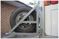
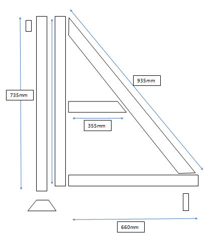
List of components 1 - 50*50*1.5 Square 735mm
1 - 50*50*1.5 - 725mm
1 - 50*50*1.5 - 660mm
1 - 50*50*1.5 - 935mm
1 - 50*50*1.5 - 355mm
1 - 40*40*3 angle - 70mm - external top mount
1 - 65*65*5 angle - 150mm - main bottom mount
1 - 30*5 flat - 60mm - anti luce tab
1 - 60*3 flat - 100mm - internal mount for top bracket
2 - nylon bushed hinges
1 - Anti Luce Lock
3 - 100*25mm bolts cut to suit
3 - nuts to suit bolts
4 nuts and bolts to mount the carrier to the bumper
and the top mount 12mm diameter and about 30mm long
I bought the hinges and anti luce lock from OVESCO
and the heavy bolts from a local bolt specialist.
The anti luce lock should be available from any trailer
parts place. (This is a common device on trailer tailgates).
Bill Behan
to top
Swivel front seats ?
Has anyone got drawings or other information regarding
swivel seats for the front ? Bob
Important stuff to know DO
NOT bolt anything to the floor until you have
located the seat to your preferred driving position
and you are sure it will rotate properly without hitting
anything.
To start with, use the original mounting holes. The
engineers like this a lot.
If you can't utilise the holes at least use the
original brackets, this too is really good. But make
sure you fill the holes to stop water etc. getting
in.
Use 8mm high tensile bolts and nylock nuts.
Use 3mm plate to make the new mounts.
Check out Vehicle Standards Bulletins - used to be
called DOTARS -for everything related to engineering
in motor vehicles, trailers, etc. ( link
here).
I used Subaru seats because they had a arm rest but
the seat was too long and hit my calf all the time,
they also had a pressed metal base and formed foam
which tended to get uncomfortable after a while. So
I changed to Hilux seats. These are a lot (50mm) shorter
in the seat and have springs under the foam to give
a nicer ride, they are also a smallish seat (as opposed
to something out of a commodore).
When you find a seat simply cut the old pressed metal
mounts off and bolt the runners directly to the new
mounts you make.
Drivers side floor to rotating seat base
 2
* 370mm long 3mm plate bent to 50mm * 30mm. Note that
the bracket is over bent to suit the rotating base.
This is the rear bracket. The 50mm edge is bolted to
the floor utilising the original under-floor reinforcing
brackets. The front is exactly the same. It's all mounted
inside the frame of the rotating base. 2
* 370mm long 3mm plate bent to 50mm * 30mm. Note that
the bracket is over bent to suit the rotating base.
This is the rear bracket. The 50mm edge is bolted to
the floor utilising the original under-floor reinforcing
brackets. The front is exactly the same. It's all mounted
inside the frame of the rotating base.
Bolt the bent bracket to the rotating base.
Rotating base to seat brackets.
 This bit is going to depend entirely on the type of seat
you end up buying. I have used Toyota Hi Lux seats
because they are relatively small and they have inner
springs to help with the comfort factor.
This bit is going to depend entirely on the type of seat
you end up buying. I have used Toyota Hi Lux seats
because they are relatively small and they have inner
springs to help with the comfort factor.
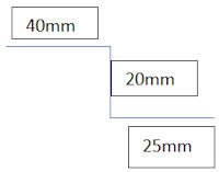
2 * 370 long *85 wide 3mm plate bent to a Z section.
Remember you need left and right brackets. The 40mm
and the 25mm are to make up for the difference in width
between the rotating base and the seat. The 20mm
is for height adjustment depending on how tall you
are. This is the right hand side bracket. In this photo
I have used a nut as a spacer to allow the slide to
run free.
 Car
seats are usually built so the driver is leaning backward
a bit with the legs extended out in front. In this
photo I have used a piece of tube at the rear to bring
the seat up to more level so I can sit more upright.
Again this is entirely adjustable to preference. Car
seats are usually built so the driver is leaning backward
a bit with the legs extended out in front. In this
photo I have used a piece of tube at the rear to bring
the seat up to more level so I can sit more upright.
Again this is entirely adjustable to preference.
When you have everything bolted together you can start
playing with where you want the seat to be located.
In cars the relationship between the steering wheel,
the pedals and the seat never line up. It might feel
good but if you get a tape measure out you'll be surprised
at how far out of alignment they really are. So when
you are playing with seat positioning don't be too
surprised to find that the seat may not be exactly
parallel with the side of the bus. I moved my seat
inboard a bit to allow it to rotate properly and then
turned it a bit (about 10mm off square) so my feet
lined up with the pedals. This also had the benefit
of giving me a bit of elbow room.
Passenger side
2 * 420mm long 3mm plate bent to 50mm * 30mm . The
passenger side is much the same as the driver side
except for the narrower mud guard. Which means the
seat is going to hang (unsupported) over the edge.
I welded a small bracket to the overhang and then bolted
the bracket onto the mudguard.
How much overhang you have is going to depend on how
much room you need to rotate the seat.
In this photo you can see how the overhang ends about
60mm past the mudguard and in line with the bottom
edge of the guard. I have also moved the seat belt
mount.
On another RB 145 I worked on, I extended the mudguard
out to level with the width of the seat which looked
really nice. But the seat belt mount was a lot of mucking
around fixing it to the floor frame and the narrower
walkway made things a bit tight.
With the passenger seat I got a bit fancy and made
the base to seat bracket on a taper to pick the back
edge up a bit. This is 50mm at the rear and 20mm at
the front. In this photo you can see the seat on the
tapered bracket bolted to the base. And the base bolted
to the mudguard bracket with the overhang nicely supported.
DOTARS has all the specifications on seat belt mounts
so double check everything. I used 3mm plate 60mm *
120mm.
The nut is welded to the backing plate and the backing
plate is riveted into position so it doesn't move when
you tighten the bolt. This photo of the passenger side
shows the seat belt mount and one of the plates that
support the overhang brackets inside. Note the rounded
corners on everything and it's all painted to prevent
rust and look a bit professional.
The gear shift
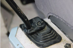
When moving the drivers seat
you will probably find that the gear shift fouls
somewhere. An easy fix is to cut it and move it sideways.
I've been told this is a common 'fix' when converting
(expensive) cars from left hand to right hand drive.
Bill
to top
Air Con woes
I had a problem with the air con compressor and the
thing froze up.
The first time this happened it shredded the drive
belts, so thinking that there was a bit of slippage
I did the belts up a bit tighter.
Then it happened again tore the rubber out of the clutch.
You can't buy these bits.
I have found a local company who can vulcanise the
rubber back into the air con clutch.
I had to make a jig to hold both the inner and outer
bits in perfect alignment but it works. The cost was
a few dollars to buy the steel for the jig and a carton
of beer for the vulcanising.
So if you have a problem with the air con clutch it
can be repaired.
Now I have to find out why the compressor is freezing
up, but I think the fans are not working.
The company I found to repair my air con clutch is
called WEARX at Hexham, not far from Newcastle. http://www.wearx.com.
They do not repair air con clutches but they do vulcanise
rubber so they said they would do it for me if I made
the jig to hold the two pieces in perfect central alignment.
Put that info onto your resources page for future reference.
Bill
An update to my earlier air con problems. It turns
out that the reason for the unit 'freezing' up was
actually the magnetic clutch bearing. Mike Varley from
Mt Isa (on our list) pointed me in the right direction.
The bearing is a massive 2 race unit and literally
half the bearings were missing. This was causing the
pulley to stop turning and thus destroying the drive
belts.
It could sit and idle all day and the pressures were
all correct which was why all the air con specialists
I went to could not find anything wrong with it and
suggested that the air con pump had a problem. Not
one of these specialists suggested looking at the clutch
bearing.
to top
Wheel Winder Part Required
Does anyone know where I could procure the eccentric
spindle that winds up the chain to lift the spare wheel
? Ron
Something off a another model should fit. May require
slight modification but a sample or a picture to compare
would be req'd. cost would be $75 inc gst

After contacting many wreckers around the country I
had no luck.
On a recent visit to NZ, I looked on line and talked
to a couple of truck wreckers.
As I drove around I visited one in Taranaki, just north
of New Plymouth, and he also did not have one, but
suggested I try one off an old Mitsubishi truck. I
took the whole unit back to base by Qantas hoping the
spindle would fit, as it looked by eye to be good,
but on removing the old unit found the second hand
Mitsy unit is identical and fitted exactly. Looks like
the Chinese are not the only ones to use parts universally
between companies.
So contact Peter above and he will send you a part
that fits.
Ron
to top
Brass Slippers for Springs
I have just replaced the brass slipper plates in the
springs on my bus. To do this I had to make a little
jig to put the locating dimple in the plate (this just
holds it in place in the spring).
The front springs have to come out to fit the plates
(it's not that hard a job and if you need bushes you
may as well do it while you are there). I haven't fitted
the rear yet but I think it can be done in place by
spreading the leaves.
If any one is feeling keen and you want to do this
I could make them for you. One metre of brass costs
about $50.00 plus delivery and and I need to pay for
the use of oxy to heat it up enough to work it to shape.
I reckon I could make a set for $100.00 plus delivery
to you.
By comparison Hino tell me there are none in Australia
and wanted $68.00 for each slipper plate. There's 16
of them.
Bill
to top
Wreckers
It seems difficult to find wreckers for our Hino buses,
and not just in this country.
This maybe as a result of the great reliability of
our machines.
So in summary this is what I have found -
Firstly look at the links
page for possible places.
Secondly, any wrecker for small to medium Japanese
trucks should be tried, as often parts for other makes
of Japanese trucks are interchangeable with Hino, for
example Mitsubishi, Nissan, etc.
And thirdly, spend a bit of time and read all the other
knowledge based information, it is surprising the little
hints that are imbedded in these gems of wisdom, and
just maybe the answer that alludes you.
Happy hunting..
Ron
to top
Rust - Roof Line
Has anyone had experience with rust in the roof at
the front?
This appears to be a common problem with the RB 145's.
I have had a fellow suggest that the problem occurs
because the air conditioner encourages moisture to
form in that area and that is why the newer models
have vents in the roof, to get rid of the moisture
laden air.
So I am wondering if anyone has heard that explanation?
The other possible cause is moisture being sucked up
(via a vacuum effect) through the rear frame work.
I know from experience that dust and exhaust fumes
enter the bus via the rear column.
When I built the bus I was really amazed to find carbon
soot in the insulation material at least a third of
the way forward from the rear and fine dust in cavities
even further towards the front.
So am absolutely convinced that moisture laden air
gets into the area between the outer skin and the the
plastic air con liner where it condenses and sits on
the frame work and encourages rust to form.
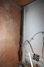
I have made several little repairs to that area but
I realised the problem was never going away. I ended
up removing the entire curved bit (I call it a 'hip').
Well not all of it, but a length of 2.4 metres from
the front joint .
I wasn't too surprised to find the rust had gotten
into the frame members, and that is where the trap
really exists. Everyone is probably repairing the visible
rust and not realising the rust is eating the frame
of the bus away.
I am interested in your thoughts on this issue and
if anyone is keen I could do a little 'how to' on replacing
the roof hip utilising the photos I took.
Bill
Yes I too have had rust problems in the roof area,
just above the guttering, and yes it is from condensation
which I have been told is common in the RB145's.
My thoughts are - it is caused by the cold air from
the air-con going along the roof line inside, where
the air comes out into the bus. This cold air would
cause condensation along the whole length of the bus,
the more and longer you use the air-con the more likely
you are to get moisture there, and if then you switch
off and park the bus, this moisture will eventually
cause problems.
The thing that could be done to get rid of this moisture
is to leave the fan for the air-con running for sometime
on high without the air-con going, before you put the
bus to sleep. My guess is that you would need to get
the bus warm again and run the fan for at least fifteen
minutes.
Keep the engine running otherwise the battery will
be discharged and bus batteries should always remain
fully charged to ensure long life.
I took my bus to a panel shop and had the rust cut
out and replaced with steel. I think a fibre glass
fix up job is probably a waste of time.
And yes, make sure the panel shop does check for any
structural damage.
Ron
Thanks for this.
In my bus, there is a strip (~300mm wide) of 0.9mm
opaque plastic sheeting, pushed into place between
the wall and roof rails and sealed with silicone
all the way along. This formed a smooth, curved
rear for the A/C duct.
The silicone completely covered the steel rails and
with a gap of ~20mm between the plastic and the steel 'hip' panel,
the condensation problem would have been solved.
Not sure if this was standard on all 145's but it may
also explain why there's no rust in that area. Again
ambient relative humidity helps. Cheers Bob
Hi everybody . from northern
NSW, we have had our 145a now for 10 years now we
never use the AC as I removed the motor drive belt
to it 8 years ago the vehicle is always enclosed
in a shed and now rust has broken through above the
drivers door the 145a has had little use the last
2 years as we have been having other adventures.
Food for thought? Sue
Hello Sue, The bus will have
been used before you owned it and the air-con used,
and the process of rust development will have started.
Once rust begins, it continues relentlessly using
any atmospheric moisture until its presence is shown,
nothing stops it except complete removal, so inside
storage may slow the progression but it will not
stop it. Sorry for the bad news, but you have to
live with the problem and in time it will show in
other places. Kind regards, Ron
Dear Ronald Thank you so much
for your response it was very informative. I did
eventually get the downloads off the site and they
are most helpful. My dad, Allan, also managed to
get the part he was seeking. What a great site you
have and so very helpful. You are to be credited
for the effort you have put into it. Thanking you
kindly Yours sincerely Deborah Khan and her father
Allan Coleman.
to top
Refrigerator fire
Hello everyone Bad news.
I have just experienced a fire
at the rear of the Dometic 3 way fridge.
Fortunately the damage was limited to the fridge insulation,
the timber cabinet enclosure and the roof vents are
melted.
 I
was lucky to be next to the bus when someone came
and brought my attention to the smoke coming out
of the roof vent. The fire was caused when the cooling
system on the fridge started leaking at the base
of the flue, this leak released the ammonia and nitrogen
mix and when I turned the fridge to GAS and lit the
pilot light the pilot ignited the nitrogen ammonia
mix. What actually caused the vast majority of the
damage was the fact that the timber cabinetry surrounding
the fridge caught fire. So even after I turned off
the LPG to the fridge the timber kept burning. I
was lucky to be next to the bus when someone came
and brought my attention to the smoke coming out
of the roof vent. The fire was caused when the cooling
system on the fridge started leaking at the base
of the flue, this leak released the ammonia and nitrogen
mix and when I turned the fridge to GAS and lit the
pilot light the pilot ignited the nitrogen ammonia
mix. What actually caused the vast majority of the
damage was the fact that the timber cabinetry surrounding
the fridge caught fire. So even after I turned off
the LPG to the fridge the timber kept burning.
What have I learned from this
experience?
If you smell ammonia it is not the toilet or cleaning
fluid, it is the fridge leaking, my eyes started to
water and I still didn't realise what it was. How slow
can I be?
If the fire alarm goes off, it does so for a reason
and it needs to be investigated. I couldn't see or
smell any smoke and I thought it was a nearby smoker
combining with the fumes I thought were coming from
cleaning fluid.
The insulation foam in the refrigerator
will not support fire, if you take the fire away
the foam will not burn.
The cooling unit of the fridge
is remarkably fragile. The unit is tack welded to
a frame and these little tacks crack due to vibration
and allow the entire weight of the cooling unit to
hang on the boiler, that's the bit at the bottom
of the flue where everything joins up.
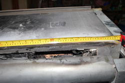 What
am I doing next. I am going to line the fridge enclosure
with a sheet of sign white. This is a metal sheet
used in the signage industry and is only about half
a millimetre thick so it doesn't weigh much. In the
event that I have another fire the sign white will
stop the timber cabinet from catching fire and this
will dramatically lower the risk of major damage
or a complete wipe out. It will also make the enclosure
look a whole lot smarter with a nice smooth white
finish. Repairing the fridge insulation is remarkably
easy and I am taking photos as I go, for future reference.
I have also found a video of how to remove the cooling
unit from the fridge. Again this is extremely easy. What
am I doing next. I am going to line the fridge enclosure
with a sheet of sign white. This is a metal sheet
used in the signage industry and is only about half
a millimetre thick so it doesn't weigh much. In the
event that I have another fire the sign white will
stop the timber cabinet from catching fire and this
will dramatically lower the risk of major damage
or a complete wipe out. It will also make the enclosure
look a whole lot smarter with a nice smooth white
finish. Repairing the fridge insulation is remarkably
easy and I am taking photos as I go, for future reference.
I have also found a video of how to remove the cooling
unit from the fridge. Again this is extremely easy.
Repairs I have taken the cooling
unit out of the fridge and a new one is being made.
This is done by Alternate Gas Refrigeration in Arndell
Park in Sydney. This is the only company in NSW that
does this type of repair and all caravan shops and
fridge technicians send fridges here for repair.
I'm just cutting out the middleman.
I have cut out the fire damaged
urethane insulation and replaced this with a similar
product. The silver sisilation is there to reflect
heat and also prevent any damage to the very soft
urethane. I can't get a small quantity of the heavy
paper based stuff as original so I am using something
lighter but it will work.
Why not just get a new fridge?
There's nothing wrong with what I have, if you ignore
the fire damage and the fact that it no longer cools
anything. A new fridge is $3,000.00 and I have been
told they are being made in China and the quality
is not there.
The company in Sydney do these
repairs for a living and I am confident that it will
be better than a new unit. The replacement cooling
unit is about $1,000.00, so I should be able to replace,
repair and mend all the bits for well under $1,300.00.
It gives me something to do and I have learned a
whole lot of new things.
My recommendations. Take your
fridge out and have a look at the little tack welds
to see if they are broken. This is important because
it happens a lot more than we are told. Some fridge
units are delivered with tacks missing or barely
there.
Secondly and most importantly,
line your fridge enclosure with something that will
not catch fire and make a little gas fire into a
major inferno.
Taking the fridge out is also
quite easy, there are only four screws at the base
and 2 at the top and it simply slides out.
Bill
The fridge repairs are going
well and I thought I would share these links in case
anyone gets really keen about fridge modifications.
The cooling unit simply pops
out of the back of the foam box. http://www.dreampod.net/index.html shows
how to put a heat extraction fan and thermostat on
the outside of the fridge and a circulating fan inside
the fridge to help keep the air moving and reduce
ice build up on the fins.
http://rvrefrigeration.com/training-videos/ an
excellent range of videos designed to train people
on all aspects of gas fridge operation.
 Don't
ever be afraid to pull the fridge apart, it is simply
a foam box which is covered in insulation material
with a plastic liner which is only 0.5mm thick. Don't
ever be afraid to pull the fridge apart, it is simply
a foam box which is covered in insulation material
with a plastic liner which is only 0.5mm thick.
I have also attached some photos
of the repairs I did a few years ago when the tack
welds broke off or the cooling fins broke. I don't
really recommend this type of repair, but it did
the job.
 Please
note that the wrap around bracket on the top right
corner was not too good because it still allowed
the tube to move up and down. The point is that the
tiny little tacks that hold the cooling unit to the
frame often break and it is probably worthwhile checking. Please
note that the wrap around bracket on the top right
corner was not too good because it still allowed
the tube to move up and down. The point is that the
tiny little tacks that hold the cooling unit to the
frame often break and it is probably worthwhile checking.
Bill !
to top
Insurance
Question - I've been looking for insurance but can't
get much sense out of them when they hear it's a converted
bus.
Answer - If you join the CMCA www.cmca.net.au then
as a member you can get insurance from Ken Tame, this
is not necessarily the cheapest, but most definitely
the best, check it out.
I have been a member for the last six + years and had
to claim twice, windscreen and accident, never a question.
Mine as you know is a converted bus, all RB's are of
course. It's the norm, not the exception.
Ken Tame and Associates.
t: 03 9853 5555
f: 03 9853 5554
e:
w: www.kentame.com.au
POB 2390 Kew VIC 3101
to top
Sway Bars
Bill wrote - There is a difference between the Australian
RB145K and Grey import RB145A anti sway bars.
The K model has a 40 mm anti sway bar and the A has
a 34 mm anti sway bar.
If you have a problem with swaying in your model A
bus, it maybe worth infesting in upgrading to a 40
mm sway bar.
I had my 40mm rear sway bar made by Signature Sway
bars at Nowra for about $600.00.
I had to send him the original to copy and it took
about 3 weeks, but he makes the bar at Nowra and then
sends it to Adelaide for heat treatment.
New sway bar mounts and bushes. I went to a truck wrecker
and found a 40mm truck Sway bar. I then cut the mounts
off the truck unit and fitted them in place of the
existing Hino units. I think that cost about $50.00.
(Yes there was a bit of cutting and welding involved).
Signature Sway bars can make some mounts for you if
need them to.
Swaying Hino Rainbow RB145R Fellow
Hino Drivers,
I built our Hino about 7 years ago, have only traveled
30.000km since complete. I posted a blog about 5 years
ago in CMCA forum to help Hino owners solve the Swaying
problems with this imported vehicle.
I got together with the engineer for Bents Engineering
who copied my old bar (34mm) and made a (42mm) bar.
This worked a treat. No other modifications were made
to the bus, Shocks & springs all original. Bents
have informed me they have built 20 bars since, all
with positive feedback.
Bents also supply 42mm poly bushes to suit the bar.
So before you spend a lot of money on new springs & shocks,
try fitting a new bar. It will work.
Regards Bob & Di.
I bought an imported RB145 around
five years ago and experienced the swaying issue.
We put new adjustable shockers on but this did not
resolve the sway. Doug
That bar will fix the sway,
but inevitably changes the way the bus handles in
an emergency swerve situation.
See my Tech Notes in March 2013 issue re just how and
why.
Collyn Rivers
Ed's Note : Ron's Rb145A has
40 mm front, 34.5 mm rear sway bars - never had sway
problem.
to top
Sway / Roll Solution
This is a dissertation subitted by Paul Carter, new information here, thank you Paul, we are all much indebted to you.
Paul Carter
(Sandy's Partner)
My Hino rolled very badly when I first purchased it so I have done quite a lot to reduce it, including.
Adjust the steering box.
New Wheel bearings (did the brakes while I was in there)
Fitted vortex generator to the rear
Played around with tire pressures.
I have it to the place where it is good to drive. Cross winds or another heavy vehicle coming the other way are just not an issue. But there are still traces of the issue still there.
I have read a bit about the orientation of the rear springs and have been giving that a lot of thought but until now could not get up enough courage to do it. The final nudge came when I read an article on another platform from someone in Christchurch who had modified his own bus and has gone on to do several others. The brief, but very informative document.
To summarize, in most leaf spring setups the swing shackle is at the rear on both front and rear axles, this means that when the spring compresses both axles moves back slightly but stay aligned. In the rear engine Hino's the rear spring set is in the other way around with the swing shackle at the front so when both spring sets compress when the bus rolls to one side on an uneven surface the front and rear axles move together just like the steering on a skateboard and thus the roll problem.
Got the first side done and all buttoned up now starting on the other side. I had to purchase a torque multiplier off ebay to get the spring bolts undone. They are crazy tight. Am replacing the bushes in the fixed spring end as they are a bit loose. Also fitting new U bolts as these are stretch to torque and as such one time use. Got them made to measure by archer springs, the price was reasonable and 24 hour turnaround.
Second side done. Went for COF this morning and drove over every bit of uneven surface I could find. Nothing, not a hint of it's former behavior. I can 100% vouch for this as a complete remedy. There are a few things I would add to the document.
1/ Fit new U bolts. ($130)
2/ If yours is the earlier version like mine the nuts holding in the front (shackle end) are not captive inside the chassis rail and will turn on you once you can get them to turn. just cut the heads off and fit new bolts,(only if they are not captive) minimum grade 8 (not 8.8) and push the bolts through from the inside of the chassis rail because you will be there till hell freezes over trying to get a socket inside there to do them up if you put them in from the outside. The back are captive but are also very tight. Get you hands on a torque multiplier.
3/ I replaced the fixed end spring eye bushes, why not while the spring is out laying on the ground. ($80)
To summarize my reading on the problem, in most leaf spring setups the swing shackle is at the rear on both front and rear axles, this means that when the spring compresses both axles moves back slightly but stay aligned. In the rear engine Hino's the rear spring set is in the other way around with the swing shackle at the front so when both spring sets compress when the bus rolls to one side on an uneven surface the front and rear axles move together just like the steering on a skateboard and thus the roll problem.
Below is the text I came across on line.
Subject: RE: Hino roll,
Hi Matt, I have now altered 6 of these narrow body Hinos, including 1 that I had and a mates which rolled quiet badly. And yes, we went through all the remedies on Facebook, magazines etc ( New tyres, stiffer springs, new Shocks, wheel alignment) but nothing worked, and generally aggravated the problem.
If you are handy mechanically this will save a lot of money. If you look at the makeup of the suspension on rear engine Hinos, 7, 8, & 9 metre, you will see that the shackles are on the rear of the front springs, but are on the front of the rear springs. So, when you drive over uneven surfaces the 2 axles are ether pulling together or spreading apart causing the rolling motion.
The cure, move the swinging shackle to the rear of the spring by turning it 180' or end for end.
Jack up your bus and block up the towbar or rear of chassis away from the springs so the wheels are clear of the ground. Remove both sets of rear wheels, remove the sway bar links and push sway bar up out of the way, undo lower shock absorber mount and push away. drop one end of the drive shaft.
Put an extended jack under 1 side of the diff housing, and undo the U bolts, lower the diff slightly to clear the spring. Undo the shackle pins from the chassis ( on early Hinos there was a nut inside chassis, later ones had a lock plate on outside) remove the spring, loosen the centre bolt and turn the leaf for the sway bar around. Refit the spring with the shackles now at the rear.
On reassembly insure the driveshaft still has at least 5 to10mm of clearance when fully closed, if not pull apart and cut a small amount off the spline as this process shifts the diff rearward aprox. 10 to 15mm.
It is critical that the pinion angle and rear gearbox flange angle are as close as possible to stop drive line growl. We just used a simple inclinometer app off our cell phone.
To line up the drive shaft properly you will need to obtain a pair of wedges, on our first bus we got some wedges from our local truck wheel alignment guys, but we then had them made by WEDGETEK engineering, 34 Klondike drive Hornby , Christchurch. Phone ( 04 ) 3499931. Cell. 021-383779 these wedges by memory are 5 deg and were about $35.00 pair plus freight, you will need to let them know the size and centre bolt hole size. The wedges are 175mm long by 60mm wide with a 22mm hole for the centre bolt and are "5 degrees" .
You just need to reassemble and repeat on the opposite side.
Believe me this is the only cure for Hino handling. It is a personal choice whether you have an extra leaf in the front springs or not. If your suspension is standard now, I would turn the springs first. Not sure what shock absorbers you have but adjustable POWERDOWN shocks set on firm work very well, also check to see if your sway bar bushes are in good order
You will not believe the difference to the ride and handling this work makes. I ran my front tyres at 65psi and the rears at 75psi, on 650x16 tyres, which makes for quiet and soft ride.
to top
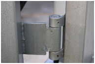
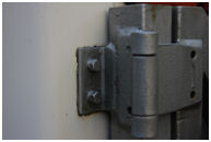
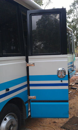
Door Conversion
Conversion of Hino RB145 entry door from sliding to
hinged.
This conversion was decided
upon to improve the overall access to the bus, without
the effort required and the associated noise which
was a part of the original sliding door.
My door was suffering problems
which included worn runners on deformed brackets
and cracks in the inner door pressing, above and
below the middle runner port and next to the lock
mounting.
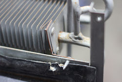
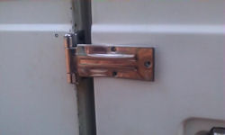
As a part of the conversion,
I strengthened the door inner skin by welding both
the cracks and a sheet metal patch into the middle
runner port, using a wooden jig to keep the door
the correct shape. It will be noticed that the door
is not straight. The lower half is slightly curved
while the upper half is canted inwards. This dictates
that the hinges must be fitted between the upper
and lower body grooves, in order to keep the two
hinge-pins perfectly in line and allow free movement
of the door.
Tools required:
1 Various hand tools, files, hacksaw etc.
2 Metric spanners or sockets 12mm, 14mm, Phillips #2
screwdriver
3 Power drill and suitable bits 3,5,8.5 & (13.5mm)
diameter. This diameter will depend on the rivnuts
selected.
4 Rivnut setting tool
5 Welding and sheet metal facilities (or a friendly
panel beater)
6 Multi-tool with steel blade / angle grinder / reciprocating
saw/cold chisel etc.
7 Anything else
The required components are
as follows:
1 2 off Heavy duty over-seal type hinges (obtainable
from Dunn & Watson, IRS, UES or others)
2 2 off Aluminium spacers 2mm thick (See sketch and
pics below)
3 2 off Aluminium spacers 3mm thick ( " " )
4 2 off Reinforcing brackets to fit hinge mountings
inside door ( " " )
5 1 off Reinforcing bracket for new lock mounting inside
door ( " " )
6 8 off M8 Steel long rivnuts, large flange
7 4 off M5 x 12mm pan head screws and nyloc nuts
8 5 off M8 x 30 button head high-tensile cap screws
9 6 off M8 x 20 button head stainless steel cap screws
10 6 off M8 Nyloc nuts
11 12 off M6 Steel rivnuts
12 1 off Outside door handle to suit (Eberhard 4-21100-K
or similar)
13 1 off Inside door handle to suit
14 1 off Lock unit (Eberhard 1-400-L or similar)
15 1off Lock striker pin (Eberhard ....... or similar - to
suit lock)
16 1 off Striker pin mount (See sketch and pics below)
17 12 off M6 x 25 High tensile set screws
Method Preparation:
1 The door auto-operator can be removed from under
the bus.
2 The door control unit, just inside the door on the
right and its dashboard mounted switch can be removed.
3 Remove the door trim panel (may be re-used in original
or modified form)
4 Remove the glued-on sealing rubbers from both the
body and the front edge of the door.(may be re-used
if in good condition)
5 Remove the lock striker pin.
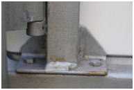
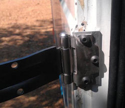
Hinge installation
1 For setting the hinges in the correct locations,
leave the door mounted on its sliding runners at
this stage.
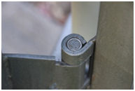
2 The hinges used in this conversion are heavy-duty,
stainless steel 'over-seal' type. It is advisable to
modify the body tab of the upper hinge to enable three
fixing bolts to be used instead of two. It is the upper
hinge that will be in tension due to the weight of
the door. Offsetting the third hole achieves a triangular
footprint for a completely rigid mounting. As in the
pic below, an additional piece of 4.5mm stainless steel
was welded to the original hinge tab to allow the third
hole to be offset.
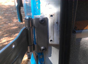
3 In order that the outside of the door finishes level
with the outside of the body, it is necessary to measure
your hinge offset. Place the hinge flat on a level
surface and measure the height of the centre of the
pin above the surface. This is the measurement that
the hinge pin must lie outside of the body face.
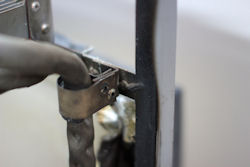
4 The location of the hinges was chosen to maximise
the distance between them.
It was decided to mount the body tabs to the rear face
of the 'B' post. To ensure that the hinges are mounted
perfectly in line, it is best to bolt them to a suitable
piece of steel bar or angle by their door tabs. This
allows the hinges to be set square to the piece of
steel, and the two hinge pins kept in line while they
were offered up to the body to mark the fixing positions.
5 Examination of the mounting face shows that where
the nearside body panel and the front edge of the door
opening panel come together on the 'B' post, the surface
is not level. To achieve a level mounting for the hinge
tab, a 2mm thick spacer was made from aluminium sheet,
with its innermost edge filed to achieve a fit against
the raised surface. (See pics below)
6 Large-flanged, steel, M8 long rivnuts were fitted
through the 2mm spacer into the 'B' post. Mine required
a 13.5mm hole diameter, but do check what your chosen
rivnuts require. At this point the total metal thickness
is comprised of the 2mm spacer, the body skin and the 'B' post.
This total ~5mm requires the use of long-series rivnuts.
7 To allow the 3mm thick aluminium spacer to fit between
the hinge tab and the rivnuts, it was necessary to
counter-bore the rear face by about 1mm to clear the
rivnut flanges. I did this using a router bit in the
pillar drill with everything clamped firmly in place!!
 8
With the upper hinge secured by two M8 screws, the
third hole can be drilled as a pilot hole through the
hinge into the 'B' post. After removing the hinge and
3mm packer, this hole will then require to be drilled
out to suit your rivnut which can then be fitted. The
third hole in the packer will also need to be counter-bored. 8
With the upper hinge secured by two M8 screws, the
third hole can be drilled as a pilot hole through the
hinge into the 'B' post. After removing the hinge and
3mm packer, this hole will then require to be drilled
out to suit your rivnut which can then be fitted. The
third hole in the packer will also need to be counter-bored.
9 The lower hinge position does not allow a third fixing
but the original door alignment fitting should be removed.
10 With both hinges fitted to the body, the door can
be slid into its normal closed position. The door tab
of the upper hinge is then swung onto the door, allowing
the hole positions to be marked on the door.
 At
this point it should be noted that if the hinge pins
are perfectly aligned, the tab will not sit perfectly
flat on the door. The tab can be twisted slightly when
off the bus by mounting the entire length of the hinge
pin in a vice, while applying a twisting force in the
required direction to the tab. At
this point it should be noted that if the hinge pins
are perfectly aligned, the tab will not sit perfectly
flat on the door. The tab can be twisted slightly when
off the bus by mounting the entire length of the hinge
pin in a vice, while applying a twisting force in the
required direction to the tab.
11 Once the necessary adjustments have been made, the
upper hinge can be secured to the body and the three
fixing bolts tightened
 12
The first hole in the door skin can now be drilled.
I drilled through one of the marked positions at 3mm
diameter with the reinforcing bracket (see pic below)
held inside the door. This marked the bracket, allowing
me then to remove it and then drill both the bracket
and the door at 5mm diameter. 12
The first hole in the door skin can now be drilled.
I drilled through one of the marked positions at 3mm
diameter with the reinforcing bracket (see pic below)
held inside the door. This marked the bracket, allowing
me then to remove it and then drill both the bracket
and the door at 5mm diameter.
13 The hole in the reinforcing bracket was then filed
out to create a slot <5mm rearwards. The bracket
is then replaced inside the door, pushed fully forward
and secured by one M4 screw & nut.
14 The holes for the two M5 front fixing screws were
then drilled through the front edge of the door and
the bracket. Note that these screws should be positioned
inwards of the rubber door seal. With these two screws
in place and tightened, the reinforcing bracket is
drawn fully against the front edge of the door and
firmly held in place.
15 The first hole in the door skin and bracket, previously
drilled at 5mm, can now be increased to 8.5mm diameter
by drilling through the hinge tab to ensure alignment,
using light pressure, so as to not distort the bracket.
16 At this stage an assistant will be useful! With
one of you inside the bus and the door closed, the
hinge tab can now be temporarily secured to the door
by an M8 screw and nut. The remaining two fixing holes
can then be drilled through the hinge tab, door and
bracket at 8.5mm and two more temporary screws fitted.
17 With some support under the rear/bottom of the door
(I used a trolley jack), one of you inside the bus
and the door closed, the two bolts securing the middle
door runner can be removed from the inside (12mm socket).
This will allow the middle runner to be withdrawn rearwards
along its track, leaving the door supported at the
front by the lower runner and at the rear by your support,
with the top of the door kept inwards by the top runner.
18 Careful adjustment of the height of your door support
will allow the gap between the front edge of the door
and the 'B' post to be adjusted so that it is parallel.
It is also most important to check that the door is
completely covering its inner sealing rubber and that
the gap around the door is equal at all heights.
19 When the door position is correct, the lower hinge
can be swung into position and the required hole positions
marked.
20 One of these hole positions can be drilled at 8.5mm,
as before.
21 Remove the three door screws from the upper hinge
before carefully sliding the door open, while continuing
to support the rear edge.
22 With the door open, the top runner can be removed,
followed by removing the two fixing bolts from the
lower runner. The door can then be lifted from the
bottom runner and taken away for its modifications.
Door modifications
 1
Remove all of the original lock, handles and linkages. 1
Remove all of the original lock, handles and linkages.
2 If you intend to remove the original external door
release, its entire pressing can be removed from the
door skin by drilling through the eight spot welds.
3 With the pressed recess edges trimmed away, a flat
1mm steel patch may be fitted inside the door skin,
secured with countersunk head pop rivets.
4 Mark out the intended cutting lines to accept the
new lock unit. I was using an Eberhard #1-400-L passenger
restraint lock.
5 With the door laid on a padded support, so that it
is horizontal with the inside facing up. Make two cuts
down the 45° face of the door edge, above and below
the original lock location.
6 Cut along the lower edge of the original lock location,
nearest to the door flange, see diagram #.
7 Cut along the original lock location through the
two outermost lock fixing holes. This will reduce the
length of the 45° tab to allow it to be bent to 90°.
8 Fabricate the reinforcement bracket as diagram #
, and the outer cover piece, diagram #.
9 Insert the reinforcing bracket inside the door and
ensure that it fits snugly in place.
10 Mark the required fixing locations for the new lock.
11 Drill through the tab and the reinforcement for
the lock fixing screws.
12 Remove the reinforcement and apply Sikaflex Auto
inside the door where the reinforcement will go, then
insert it into its position and draw it fully into
place, using spare bolts and nuts.
13 Once the Sikaflex is fully cured (24 hours minimum),
the bolts may be removed.
14 The lock fixing screw holes can be enlarged to allow
the installation of long rivnuts.
15 Apply Sikaflex to the outer cover piece, which is
then held in place by the fitment of the 3 rivnuts.
These pull together the outer cover with the tab and
reinforcement and provide a secure mounting for the
lock. Allow 24 hours for the Sikaflex to fully cure
before continuing.
16 The Eberhard lock required a slot to be cut to allow
its operating lever to be accessed from the inside
the door.
17 The chosen Eberhard door handle also required an
installation hole which was cut through both the door
skin and the reinforcement.
18 Making and installing the linkage rods is not easy
due to the confined space and limited visibility. As
there will be some paintwork to be done after all these
modifications are complete, don't lock linkage rods
in place until you are sure they will not have to be
removed again.
19 If you are not using the original inner door release,
you may need to fabricate a mounting to suit your chosen
handle. I used the original release but added an extension
piece to make it easier to operate.
20 The hole in the inner skin where the lower runner
used to fit passes across the rubber door seal and
may now be patched, if desired.
21 On a trial fit of my door, with new pinchweld seal
rubber installed to the step, I found that the lower
inside panel of the door was bowed, allowing a gap
of some 6mm between the centre of the door and the
seal. To overcome this I cut the grill from the lower
inside panel of the door. I then inserted some wooden
packers inside the door to bring the inner panel straight.
These were then coated in resin to waterproof them
and bond them permanently in place.
22 In order to create a ventilation path that would
comply with the gas requirements, I then cut a series
of 32mm diameter holes below the seal line. Both these
and the previous grill hole will need to be covered
with suitable mesh.
23 Rods and linkages will also need to be fitted to
operate the lock from the inside. I fabricated a bell-crank
assembly to enable me to use the original lock button
in its original position.
24 The area around the patched middle runner port and
the lock position will now need some filler to bring
them to a finished level.
25 If you have removed the original external release
and patched the hole, a thin coat of body filler can
be applied to bring the patched area up to the original
panel level.
26 The door is now ready to be prepared and painted
as required.
Refitting the Door
 1
To refit the door, one assistant will be required,
two would be useful. Using a jack or similar to support
the weight of the door, one assistant can hold the
door upright in the open position (90°) while the stainless
steel screws can then be pushed through the hinge tab
and door and have the nyloc nuts fitted on the inside. 1
To refit the door, one assistant will be required,
two would be useful. Using a jack or similar to support
the weight of the door, one assistant can hold the
door upright in the open position (90°) while the stainless
steel screws can then be pushed through the hinge tab
and door and have the nyloc nuts fitted on the inside.
2 Until all six screws are fitted, only lightly tighten
them. The door operation can now be checked to ensure
that it swings smoothly into the correct position.
3 Once the alignment is confirmed, all six screws should
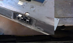
be fully tightened. Lock Striker Pin Since the new
lock has been installed at the same height as the original,
it will be necessary to remove the original pin and
its mounting, to be able to install the new pin, aligned
at 90° to the lock mounting face. To do this the original
pressed pin mount must be removed.
1 Mark the cutting lines around the original pin mount.
2 Using a multi-tool / angle grinder/ chisels etc,
carefully cut around the raised portion and remove
it entirely.
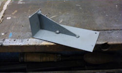
3 Fabricate the new angle bracket (diagram # ) and
mark the mounting holes on the door (C) post. (It may
be preferred to weld this bracket into the 'C' post)
4 Drill the holes into the door (C) post, enlarge to
suit your rivnuts and set them into the post. I used
M6 steel rivnuts which required holes of 9mm diameter.
5 Fabricate the new striker pin mounting, including
mounting slots to allow fine adjustment.
6 With all exposed metal faces treated for corrosion
protection, the bracket may be secured to the post
by M6 high tensile screws and with Sikaflex Auto applied
to the rear face of the bracket. This will bond the
bracket to the post and prevent any water ingress.
7 Allow minimum 24 hours for Sikaflex to fully cure.
8 The new striker pin mount complete with striker pin
can now be installed to the post.
9 Before closing the door, ensure that the unlock is
working correctly
10 When the door is closed onto the pin it should align
smoothly.
11 Adjust the position of the striker pin as necessary
to achieve a smooth operation and when in the closed
position, that the outer skin of the door is in line
with the body
Door glass
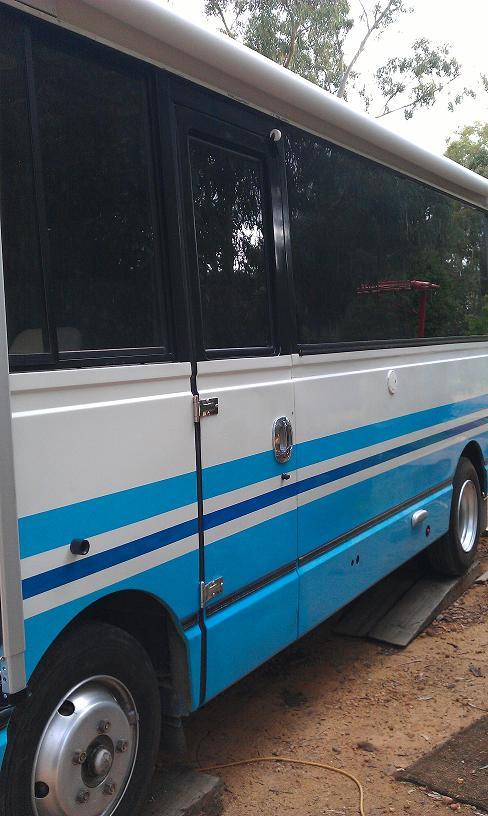 The
original door glass is 5mm thick, toughened and marked
with the applicable standard. However, it also includes
three Japanese symbols which are etched into the glass,
and therefore cannot be removed. We decided to replace
this with a new piece of tinted, toughened, marked
glass. The original rubber seal and lockstrip was still
supple after 27 years, and was able to be re-used. The
original door glass is 5mm thick, toughened and marked
with the applicable standard. However, it also includes
three Japanese symbols which are etched into the glass,
and therefore cannot be removed. We decided to replace
this with a new piece of tinted, toughened, marked
glass. The original rubber seal and lockstrip was still
supple after 27 years, and was able to be re-used.
Interior trim panel
The interior trim panel is made from sheet aluminium
and includes a pressed piece to provides clearance
for the original door handle. This can be easily
removed by drilling through all of the spot welds
and replacing with a flat piece of aluminium, riveted
in place. The original trim clips may be re-used
with new Champion inserts (#39) if required. The
original panel was trimmed with two layers of fabric,
glued in place. As the lower inside panel of our
door was quite badly marked, we decided to add
a new lower trim panel which was made from aluminium
sheet. Both panels were then covered in macro-marine
fabric trim, matching that which had been used
for the bus interior.
Was it worth it? Oh yes!!! That
soft but comforting clunk as the door closes is a
vast improvement on the whoosh, rumble, clatter and
bang that was its previous sound and, on the road,
there are no rattles.
to top
Towing Information
Under Australian regulations, an RB145 is allowed to
tow a trailer of up to 4500kgs gross mass as long as
the driver holds an MR (12T ) or higher license. Anyone
find that reg ?
Have a look at the pic
of the WA registration paper.
Courtesy Bob Wood
Have a look at this
pic of a Victorian engineers certificate for registration
It shows that the towing trailer can be 3.2 T.
PS I have read that towing capacity of a braked trailer
can be around half the GVM, or the GCM can be 1.5x
GVM
Courtesy Rob Olsen
Does anyone have more information regarding towing
regulations or hitch requirements ?
Please send, as this is important information, thanks,
admin.
to top
Intercooler
Alex and Ann Morgan have had their RB145, Harry (the
hounded) turned into Harry (the harrier) by the addition
of an intercooler by Turbo Glide (Co. details on graphs).
Air from the turbocharger has been heated by compression,
the heat expands the air this negating some of the
effect of the compression, so cooling will result in
more air being drawn into the engine, and thus more
power delivered by the engine - that's the theory.
How did it turn out ?
Alex reported "I am more than satisfied with the
decision to inter-cool Harry. We are in the middle
of a trial trip towing our 1998 Suzuki Vitara, the
temp gauge has moved less than ever before (must add
I had renewed the radiator cap) and we are averaging
17 litres a 100 km up the NSW coast, at speeds between
85 to 95 kph. The next rip averaged 16 l / 100
km.
Harry weighs in these days at 5.73 tonnes on the compliance
plate. Dyno after conversion indicated an additional
10% on previous, and this really is felt when the hills
appear."
Cost of the Intercooler and bits $763. 00, Make up
and fit, including cooling fan, air scoop etc $1520.
Wish I was a mechanic! However, a good result for me
at $2500.
Alex has kindly provided these pics of the installation
and the Dyno tune performance graphs, courtesy Turbo
Glide. (These show approximately 16% - 20% improvement
in torque and motive power at low speed of 45 km/hr
and around 20% increase in maximum power.)(the green
zone is there for a reason - Admin)
Thanks Alex and Ann, a great project, well presented,
and a joy to read - Admin
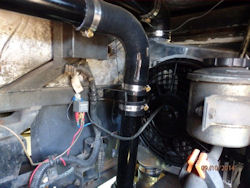
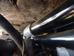

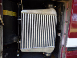
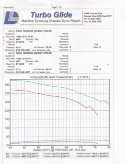
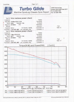
to top
VIC Registration Costs
?
G'day Ron,
I was wondering if you can tell me the cost of rego
on the RB145 in Victoria at present.
I was originally registered in Qld but have now retired
and headed south. Since I am from SA, I went ahead
and changed my Hino & car to SA rego - easy process
- only to find it was more expensive than Qld.
I have found your website very helpful and informative
- Thank you for the effort.
Have Fun
Kevin=
Hello Kevin,
Glad to see the website has been helpful to you.
Now re the rego fees.
As an indication the full fee for a Hino RB145 is about
750.00 per year, discounted to 1/2 for one vehicle
only for pensioners.
The fees differ for each vehicle dependant on insurances
based on where you live in VIC.
Also remember there is stamp duty for first registrations,
based on the original vehicle cost, not sure what %
but it cost me 1800.00 for 52,000 from memory.
To get registered is easy here also, you need to have
a VIC address and the vehicle will need to go over
a pit to be checked by a certified mechanic, VIC Roads
will tell you the closest to where you are.
Best to go to VIC Roads website and check, and give
them a call to get more exact answers.
https://www.vicroads.vic.gov.au/contact-us
Hope that has helped,
Ronald
to top
Coolant Volume for Buses
Typically, you will not find coolant volume information in Owners or Technical Manuals of buses.
The reason no information is given in any manual of buses concerning the coolant volume is that there are many versions of coolant
systems when it comes to number of heaters, preheaters and other coolant related volumetric issues, such as piping and so forth.
The only way to find the volume is to drain the system and measure the fluid volume, either on draining or filling.
Use the information on the pack of antifreeze / anticorrosion fluid for the concentration required. It is typically around 50/50 %.
Hope that helps you.
to top
Cooling Fans for Hino
RB145
Replaced the front Thermo Fans. (burnt both out) I replaced the originals with Maradyne Universal 12'' 24V 130watt Reversable Skew Blades.
Fitting is easy, 4weld on brackets & a bit of trimming on the top & bottom of the fan.
Cost about 400.00
Courtesy Hinobago
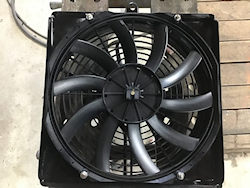 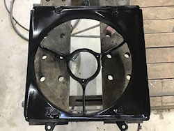
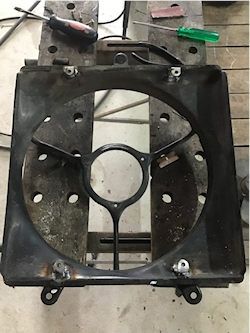 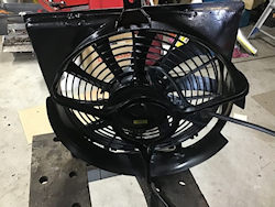
to top
Cruise control for Hino
RB145
ProServ Auto Parts
Can you supply a 12 volt cruise control add on kit
for a manual cable throttle control
And extra 24/12v converter
Admin comment - I use the throttle control when cruising
and this works fine. It is also more economical than
the cruise control unit, as when the speed slows you
do not get full throttle, thus saving fuel. On long
trips at 75 kph on West Aus roads, straight flat and
smooth, Betty achieved just over 8 kpl.
to top
Window washer nozzle
Bob the Builder has sent me a request.
"Where I can get a window washer nozzle mine was
broken during a storm and I don't seem to be able to
get one any where"
Bob replied ..
Re the window washer nozzle, the only ones I know of
are the Hiace style http://www.ebay.com.au/itm/Toyota-Hiace-89-05-Windscreen-Washer-Jet-Spray-Nozzles-Pair-/281109602542?pt=AU_Car_Parts_Accessories&hash=item41737020ee
Or the series 2 Land Rover single nozzle, it may be
easier to put two of those in - not sure, I haven't
had to look at that issue yet. http://www.ebay.com.au/itm/Land-Rover-Series-2-2a-3-Windscreen-Washer-Nozzle-Jet-Bearmach-Brand-/271429246731?pt=UK_CarsParts_Vehicles_CarParts_SM&hash=item3f32719f0b
Alternatively, on the rally cars we used to attach
spraybars to the wiper blades and run a rubber hose
from the original spot to the spraybar. Worked really
well but a bit hungry on water.
to top
Front hub removal
by Michelle Webster, Auckland, New Zealand
1987 HINO RB 145
On my assumption that if a girl
can fix her sewing machine she can fix anything this
is my experience removing the front hubs on our house
bus to inspect the brakes. We were told it was in good
order mechanically but it had been sitting for 6 years.
Maybe this isn't the right way
but as there is not much around on the net this might
help someone.
Get the manual here. Great website
for info, contact etc. Hino
RB145.com
Helpful people.. NZ Motorhome & Caravan
Forum and Community NZ
Motorhome Community
My experience removing front
hubs to inspect the brakes.
At first I thought it would
be a simple job, the workshop manual shows the drums
themselves to be a separate item like a car. Undo
a couple of retaining screws and pull them off.
Yes well.......they are
indeed a separate item but bolted on from the inside.
So .... after cleaning with
Kerosene and water-blasting everything jacked up the right
front and found that the brakes were binding.
Once the wheel is off
it is easy to see the 2 slots where the notched wheel
for the brake adjusters hide. There is an arrow on
the baking plate which indicates the direction to turn
for tightening the brakes so go all the way in the
other direction.
Note: the bolts which
hold the wheel trims on, the wheel nuts and the brake
adjusters are handed so do not mix parts from different
sides.
Backed off the brakes as far
as they would go, removed the bearing nut and outer
bearing.
The hub moved a little
bit but refused to come off.
Not only that but it then
would not even turn so put the bearing back on and
consulted the experts as to why.
I let some of the advice pass (use a big slide hammer
etc) and in the end got right up inside with a torch
for a closer look. There is enough room to see the
adjusters and confirm which way to turn them. The adjusters
still had thread showing....they had seized before
winding right down!
Some CRC using the tube thingy
that comes with the can and working them back and
forth finally got them right down with no thread
showing.
Took the bearing off again and
the whole hub just fell off.
A relief but not funny...damn
thing is extremely heavy.
I waited till morning when it
was cold then poured a jug of hot water over the
inner bearing race and it just popped off with a
screw driver along with the spacer behind it.
In the end no heavy tools required.
The brake shoes can only go
one way round so best to mark them if re using.
The retaining pins and all the springs can go either
way up so no problem with those.
Just unhook the main springs with a screwdriver.
The hub had a wear ridge, not
too bad but obviously enough to stop it coming off
unless the brakes are fully retracted. Photo shows
one of the bolts holding the drum to the hub.
Pity they are on the inside.
I put the adjusters in the vice
and would them right off then cleaned the threads
with a small hacksaw blade and a wire brush until
they turned freely by hand.
Replaced the piston cups even
though they looked ok ($5 each from Truck Stop, Mt
Wellington) then reassembled it all using blue silicon
brake grease (Autostop, Otahuhu) on anything that
moved. The main springs are a bit of a mission. I
put one end on a shoe then a piece of wire doubled
through the other end to pull the spring down using
a large screwdriver for leverage.
Don't forget the retaining pins
and springs (spring outside the shoe) and that the
shoes only go one way round. Do one side at a time
so you have something for reference.
Wash out the bearings (I used
petrol then brake cleaner) blow the out with compressed
air but do not be tempted to spin them up. Nice sound
but not good for a bearing with no grease.
Concave side innermost towards
the kingpins.
I used Locktite on the inner spacer
and bearing race. Not sure if this is the right thing
to do but was suspicious of how easy they came off.
Interference fit but warmed them slightly in the
oven first and they just popped on.
In this case the shoes, bearings
and grease seal were all in good order so they went
back on.
Required thickness of
shoes is 8-4mm, mine were 7mm.
Pays to check them closely though
as it is not something one would want to do again in
a hurry.
Re packed with blue high spec
grease (Repco). Really push it in making sure it
gets in everywhere. Use the recommended amount in
the shop manual, packing what is left into the middle
and the end cap. If new to this Google bearing packing.
The hub is heavy but not too
bad...I just managed to lift it on by myself (carefully)
Trick is to get it in position first then lift up
and on, careful not to catch the grease seal.
Torque the bearing nut up as
recommended in the manual and don't forget a new
split pin; (preload torque 80-90lb then back off 1/16
- 1/4)
Wind one brake adjuster out
until the drum wont turn then back off just until
it is free. Do the other the same.
At this point top up the brake
fluid and bleed the air out until there is resistance
in the pedal.
Tighten one adjuster right up
till the drum wont turn then back off 5 clicks. Do
the other the same.
The reason I did it in this
order was that getting the brakes to work beds the
shoes in and centers everything before final adjusting.
Then do it all again on the
other side.
While it was up in the air I
adjusted the steering box per shop manual specs.
Took all the play out but make sure it goes lock
to lock without binding. Also greased the king pins
and spring hangers.
Final bleeding of the brakes
is a pain, still not perfect but everything seems
good after a test run.
Manual recommends this is done
with the engine running.
Clean and lightly grease the
wheel studs and contact surface of the nuts
Points to note:
Make sure the brake adjusters
are indeed all the way in.
Replace the brake rubbers
anyway (says so in the manual)
Put anything threaded
back where it was as threads are handed.
Brake shoes only go one
way round.
Hino Workshop Manual page ref
(actual PDF page number)
Rear Axle p
78
Front axle p88
Steering p114
Master cylinder p143
Front brakes p161
Cylinder bore front & rear 26.99 (1.0625")
Adjust front brakes p169
Bleeding p171
to top
Radiator Hoses
Radiator Hoses for RB145A
In the Cooling System Manual
900144936 - Hino calls SZ91044425 cost $110.75 plus
GST.
900144937 - Hino calls SZ91044424 cost $83.10 plus
GST.
Mal Mckenzie
to top
Hino Water Pump
My model is the Hino Liesse, of which there are very
few in Australia, making parts identification quite
difficult.
Initial symptoms were - small fluid puddle on the ground
near the rear bumper. Investigations revealed it to
be engine coolant and found to be coming from behind
the Harmonic Balancer and seeping around the front
sump area. I immediately suspected the water pump,
but could not be sure without removing the rear bumper
and support assembly, pump drive belts and pulley.
Fluid was clearly leaking from the water pump seal.
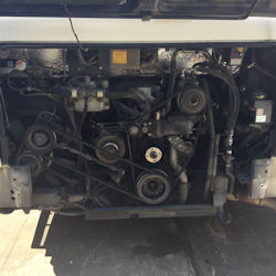 The
pump could not be identified by parts suppliers from
the photos I took and sent to them. They could not
find any equivalent local match to my engine number,
VIN etc, so the pump had to be removed. The
pump could not be identified by parts suppliers from
the photos I took and sent to them. They could not
find any equivalent local match to my engine number,
VIN etc, so the pump had to be removed.
This meant, removing all the other belts, pulleys and
the harmonic balancer, which was the hardest to remove.
When this was all done, another problem became obvious
- timing cover oil seal.
With the pump removed, I was able to take it and compare
with possible replacements. A couple were a close match
- but not quite right.
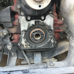 In
the end, I was given contact details for a company
that specialises in cooling system repairs including
water pump refurbishments. In
the end, I was given contact details for a company
that specialises in cooling system repairs including
water pump refurbishments.
For your reference the company is: - Auto Cooling Pty
Ltd, Factory 7, 216 Blackshaws Rd., Altona North, Vic.
Phone 03) 9362 7799.
They may be represented in other states. The cost was
$165.00 as compared to a quoted new price from Japan
of approx $700.00 ex freight.
A replacement oil seal was purchased from the local
Hino dealer for $50.00.
For those who may not be aware, there is a guy in Qld.,
who has a mate in Japan who can get a quote then supply
and ship new parts to Australia.
Parts are quite pricey depending on the exchange rate,
but if you need them, you pay for them.
His details: - Phil Jaquiery, 0438 102 002, philip@jaquiriery.net
She is all back together now and ready to rock and
roll. -:)
Steve McDonald
to top
WANO Japanese Truck Parts
G'day
I was told a few days ago that I needed new engine mounts. Being in Adelaide and having used "He Knows truck Parts" before for my 145 I googled them and found a name change to WANO.
On ringing and saying that I had a Hino RB-145 the response once again was "Okay, the little bus" Very reassuring!
Short story - I had my mounts available the next day as they were in stock.
WANO part # 1Y3120 front engine mounts RB145 - $128 ea
Wano (Japanese Truck Parts) has 17 branches in all states, and Canberra, but I have only used the Regency Park branch - ask for Rick - who has been both knowledgeable and helpful.
Kevin Sampson
to top
Speedo not working - and a fix
Hi
The speedo in my Hino Rainbow 145 Bus is not working. I have tried opening and closing the outer face of the speedo but it appears that the pins at the back of the speedo are not connecting with the cable that comes up.
Any answers please. Thanks Brian Canberra Australia
Hi Ronald
Many thanks for your email, and for taking the time to reply to me. I will take on board the details re Wano in Canberra.
As it happens, a friend alerted me to the possibility that the pins at the back of the speedo may have been "dirty", and after an application of "electrical contact cleaner" I am delighted to say that the speedo is working again.
I have owned my Hino Rainbow 145 Bus for 11 years now (it is a 1993 model) and I can say that the pins have never been cleaned during that time.
Thank you once again for considering my call for help.
Best wishes Brian Canberra
to top
|